1959 MIRROR-MATIC technical page (...)
I just bought a '59 Mirror-matic (thanks Bob L. ) and i'll install it on my '57 ... yes, i know, no mirror-matic in 1957 but, but .. Note that the # number is 1902066 on the bezel (and 1902068 on inside of the cover). General infos and messages about Mirror-matic at this page.
My goal is to have a working mirror and not a "trailer queen mirror" !!!
 So as soon as i removed from the package, i wired it to + 12 V : seems good,
when the switch is "off" the mirror has a # 1 position ("bright")
and if i switch to "city" or "highway" the mirror clicks and goes to # 2
position ("dim").
So as soon as i removed from the package, i wired it to + 12 V : seems good,
when the switch is "off" the mirror has a # 1 position ("bright")
and if i switch to "city" or "highway" the mirror clicks and goes to # 2
position ("dim").
But in the dark or in front of a 100W lamp the mirrors stays on # 2 position (dim) ... Seems it needs some adjustement. Other tests:
- I put the mirror "off" -> normal (bright) position (amperage: 0.4 A)
- I put the mirror on "city" (or "highway" in the dark -> normal position then after 15 s goes to "dim" and keep this position (amperage: 0.8 A) !!
- If i remove + 12 feed wire, goes to # 1. If i re-wire to + 12 immediatly, goes to # 2 pos. but if i wait 1 or 2 mn, no motion, then after 15 s, goes to # 2...
I decide to take it appart (i've some electronic knowledges..). How to ? See FSM (no errors):
- Remove switch knob (pull it carefully with a screwdriver acting as a lever)
- Remove the two small lower screws
- Disengage the stainless steel bezel (2 tabs at the top) from the black plastic housing cover.
- Disengage the small tabs of the cover from mechanism and push on the threaded mirror fixture to remove the complete mechanism.
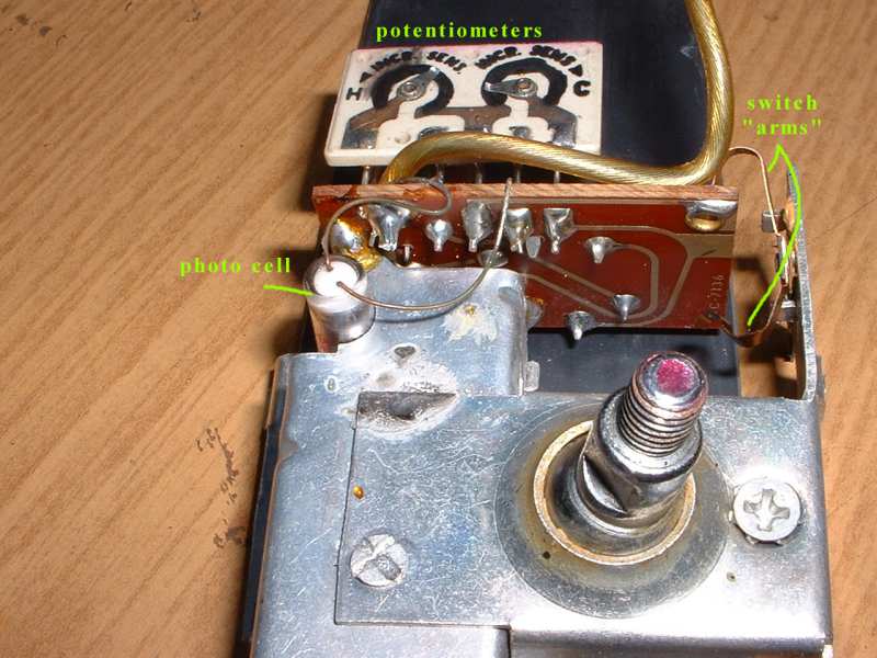
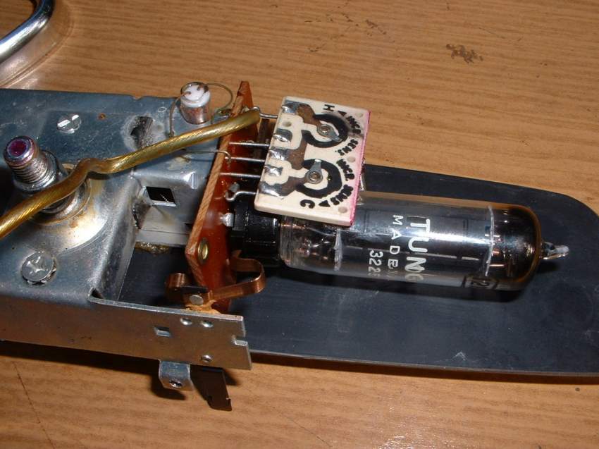
- And now look at this marvellous Chrysler "electronic" gadget !!! 2 relays, 1 tube, 1 photocell etc...
 To
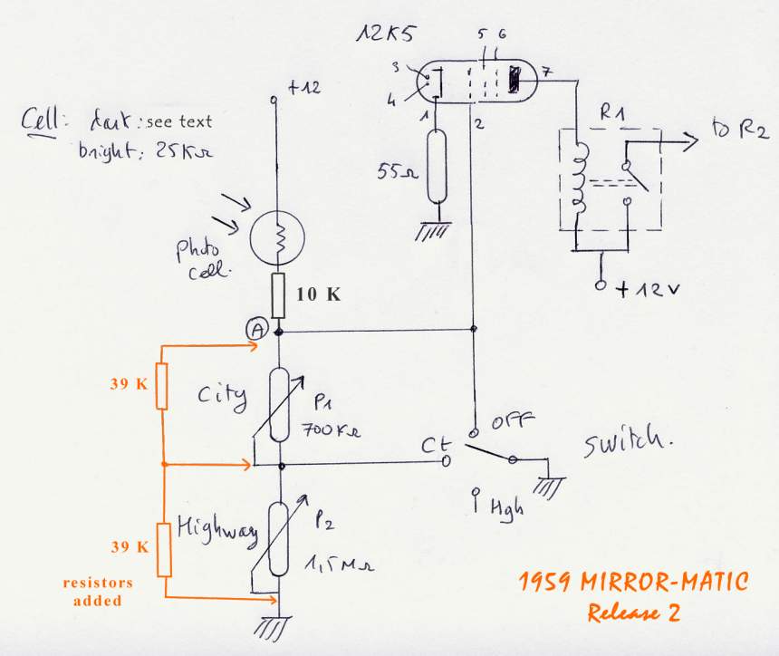
make some repairs or adjsutement, i need a schematic but no schematic glued on
the back of the cover as on radio !!! Fortunately the schematic is easy to trace
so i draw it (see pic, click to enlarge) after some hesitations:
the square potentiometers plate is in reality 2 potentiometers but also 2
resistors engraved on ceramic (?).
To
make some repairs or adjsutement, i need a schematic but no schematic glued on
the back of the cover as on radio !!! Fortunately the schematic is easy to trace
so i draw it (see pic, click to enlarge) after some hesitations:
the square potentiometers plate is in reality 2 potentiometers but also 2
resistors engraved on ceramic (?).
I fyou're familiar with electronic, perhaps you don't know well the "tubes
technology" . The 12X5 tube (pentode but used as a triode ) acts as a trigger
switch / amplifier. When the grid (pin 2) is under a definite value (adjustable
with P1 and P2) the tube acts as an "open switch" so the R1 relay is "off" and
so the R2 solenoid: mirror is in release (bright) position.
When the grid voltage exceeds this value (because photocell has a lower
resistance if exterior lights strikes it), the 12X5 acts as an amplifier or as a
"closed switch"; R1 closes and closes the R2 solenoid which "pull" the back of the
mirror to "dim" position.
I took some measurements
. Remember, the values of resistors which are
on the schematic are the values i've measured with a multimeter and not the
factory values !
If someone has them, let me know...
30/6/2003 - Conditions of test: mirror feeded with + 12 / position : "city" / mirror glass on the bench (cell in the dark ..) / as described at the beginning, after 15 s mirror is in (non correct) "dim" position
After some "no result" tests i decide to fully "out-of-align"
the "city" potentiometer (easier because ther's only 1 potentiometer in this
position, the other is grounded). Near the extreme end of the travel (lower
resistor) the mirror goes to "realease" ! I measure at "A" (see
schematic) the voltage = 1.7 V. I turn a little the potentiometer to increase resistor, immediatly the mirror
switches to "dim". 2.5 V at A.
 So i turn a little back, mirror "release", again 1.7 V at A. I take the mirror
in my hand and direct it to my bench light. Immediatly the mirror "dims". I put
my hand on the cell opening, mirror "release" ! Magic, it works !!!
So i turn a little back, mirror "release", again 1.7 V at A. I take the mirror
in my hand and direct it to my bench light. Immediatly the mirror "dims". I put
my hand on the cell opening, mirror "release" ! Magic, it works !!!
The adjustement range of the potentiometer is extremely small, perhaps 1/10 inch .. I think that potentiometer values have changed and increased a lot. To have the 1.7 V, with some arithmetics, you find that the resistor of P1 must be 25 K (i measure the value: around 30 K) and i've a 700 K potentiometer ... I'll solder a resistor (50 to 100 K) in parallel with P1 to have a larger range of adjustement.
I make the same test with "highway": same conclusion, P2 is still higher than P1 ! I made some other tests and it seems that the critical value of "A" voltage is around 1.9 V. At this value itsn't sure that mirror "releases" at each time.
So i must set the A voltage to 1.7 to 1.8 V in "highway"position (it's the most sensitive position) and to a lower value in "city" position. Problem is to make the right adjustements because you can't adjust with mirror in the car at night (and your friend who follows you in another car with headlights on !)
01/07/2003 - second
test. Condition of test: same as 30/6. I solder a 39 K resistor
in parallel with each potentiometer and test the mirror. Strange,
voltage at "A" are different than yesterday ! Sometimes i read 1.4 V, then 1.1
then 1.9.. It seems that the voltage isn't steady. And every time i adjust P1
(or P2) the voltage becomes odd, i.e if i decrease P1 the voltage sometimes
increases sometimes decreases ...
It takes me 1 hour to understand: culprit is the photocell !! I thought that
only the front of the cell was sensible but no ! ALL the photocell (which is in
a clear glass) reacts to light. So every time i move my hand near the
potentiometer (or the weather becomes cloudy or fine , the exterior door of my
room was opened..), the resistance of the photocell decreases or increases..
FORGET the 1.7 V or 1.9 V, this value is correct for a certain amount
of light.... If you make the test in the dark you can't have more than
0.7 V "highway" or 0.4 V "city" at "A".
The only fact is that the system goes to "dim" when you've 3 V at grille (0.5 V less than at the cathode). Other fact, the resistance of the cell in the dark is 60 K WITH the 12X5 tube on socket (and no voltage supply ..). I'm WRONG ! I've the filament of the tube in // with the cell ! If you remove the tube, the correct resistance is around 10 Mo !!
so, How Chrysler adjusted the Mirror-Matic ?
01/07/2003 (night) - 3rd test. I wait until the night to test the mirrormatic. I put the unit at the far end of my garage and drive my Buick ahead of it (at 10 meters or 30 feet). The mirror works well but only if the car is in high beam. If i switch to low beam, the unit works in "highway" position" (not every time) and not in "city" position. Seems that i 've too cushioned the cell with the two 39 K resistors.
02/07/2003 - 4th test. I remove the two 39 K and put in place a 82 K (// with P1) and 100K (// with P2) . I adjust the potentiometer to have a equivalent resistor of 45 K for P1 and 70 K for P2. The unit seems more sensitive, if ther's some (exterior) light in my workshop the unit (in "highway") switchs immediatly to "dim" and doesn't released until i hide the cell. I must wait until night to test like yesterday.
02/07/2003 (night) - 5th test . Last test (?) the mirror now works like a charm but i must test it on the road. So i install it in the car (need a small hole in the base for the wire). The wire is connected to "H" pin of the headlight switch (Hi-Lo beam) . I insert a 4 A fuse in the wiring ..
To be continued ....
Click to enlarge
 |
 |
 |
|
|
 |
 |
| R1 relay and cell | tube, potentiometers & printed board | Sparton manuf. | plastic housing and advises.. | potentiometers and suppl. resistors. | the official "instructions " (thanks Frank) |
actualised 24-août-2011
